ArduinoUploader which gave me a lot less trouble. (Local Mirror)
ArduinoUploader:
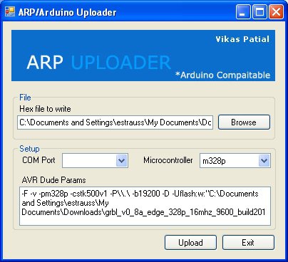
Implement:
- Browse to find the GRBL .hex file that you downloaded from the above instructions.
- Note that in the image no COM port is selected. Select the COM port that corresponds to your Arduino.
- For "microcontroller" you really should be using "m328p". Using an Uno will ensure this happens compared with using an old Duemilanove which may or may not have a 328 chip. GRBL 0.51 and below can run on a 168, but with a greatly reduced list of features. Don't bother, get an Uno Rev 2 or Rev 3 and make it easy on yourself.
- The baud rate shows up as 19200 in these settings. This also gave me trouble on my machine running Windows 7 64-bit. The solution was to change the COM port speed to 115200. This is done in Windows under: Control Panel> System> Device Manager> Ports> Properties. I then altered "19200" in ArduinoUploader to "115200", clicked upload and everything went to plan. It may work for you with all settings switched to 19200. Your mileage may vary. For the black DK Duino, 57600 was effective.
Shield Construction:
Building the shield is covered in a series of videos best referenced in order in their playlist.
Driver Boards:
Driver construction is outlined in #04 in the video tutorials. The power and USB cables should not be connected to the shield or board. Break in half the headers included with the driver boards, and insert them (long pins down) into a set of sockets on the finished shield. The small boards can then be soldered to the short pins. Repeat for as many boards as you have. Place the boards in the sockets corresponding to the X, Y and Z-axes. Note the small, silver potentiometer on the board must be closest to the edge indicated by the text on the shield: POT-->>.
At this point, you would want to connect the motors to the shield. Again, make sure that there is absolutely *no* cabling or power rigged up to the Arduino at this point. Using the Sparkfun motors recommended for the project, the colors get attached in this order for each set of terminals that has a corresponding board in its socket: from left to right--green, black, red, blue.
Hardware Configuration:
Now that everything is hooked up, you'll want to set the driver boards so that they are allowing the right amount of current through to the motors. Attach the remaining stacking headers, the ones with the really long pins, to the bottom of the shield. There are two with six pins and two with eight pins. Make sure to match them up correctly. Now insert everything in to the Arduino. There may be empty sockets on the Arduino once you plug in the shield. That's ok as long as the empty sockets are towards the end of the Arduino with the USB and power supply connectors. There should be NO empty sockets towards the other end.
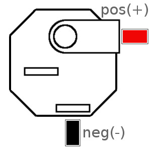
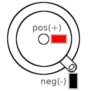
With your power supply unplugged from the wall, connect the DC side of the supply to the shield. Make certain to heed the positive (+) and negative (-) symbols on the board and attach your power leads accordingly.
If using one of our kits with the included power jack, follow this schematic for soldering and attaching your power leads:

If you wish to get the most precise movement you can out of your motors, then you want to use microstepping. This allows your motors to be driven at fraction of their rotation. For example, 2x microstepping (or "half-stepping") gives a 200 step motor 400 steps. This is great for precision, but does reduce torque. More precision, less torque. Less precision, more torque. Got it?
If you would like to take advantage of the driver's full 16x microstepping then the included jumpers should be added to the center jumper headers (measuring 2 pins by 12 pins). Each of the the sets of pins, labeled 1, 2 and 3 on the X and the Y Axes should get a jumper for a total of 6 jumpers total.
Here is the truth table for jumpers, in case you want to decide on your own settings. "MS1" is simply labeled "1" on the board, and the same for "MS2" and "MS3".
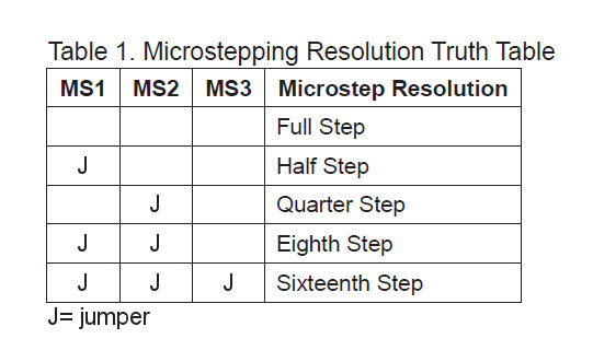
Using all three jumpers on each axis configures the drivers to run the motor at 16x microstepping. The small, silver potentiometers on the individual driver boards must be turned all the way down, that is counterclockwise, before powering on. The chip can be smoked otherwise.
The power supply can now be plugged in to mains power.
Press the RESET button on the shield and you should here a slight tapping/whirring noise in the motors as the Arduino reboots.
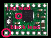
Using your multimeter set to Volts, the tip of the red lead should get placed into the tiny, unused via in a driver board. The black lead should then be placed towards the small soldered pin closest to the motor wires and at the corner of the board nearest both the wires and the potentiometer. Using a small screwdriver, this reading needs changed until it satisfies this formula: V = I * 0.4. That is the Voltage you read should equal the Amperage (I) for each coil in your motors after being multiplied by 0.4.
The recommended Sparkfun motors are rated at 1.6 amps. So, V = 1.6 * 0.4 gives us 0.64 volts. That is what the multimeter should read between these two points. Repeat for each driver board.
Heat Sinks:
To ensure solid adhesion of your heat sink to the diver chip, you should clean the top surface of the IC. Disconnect all power to the project. Using pharmacy grade alcohol, 90% is recommended, dip a cotton swab into the liquid, blot the excess on something clean and absorbant, then rub the top of the chip in small circular motions. Follow this by rubbing the chip using the dry side of the swab to complete the cleaning. Repeat this for each driver chip and allow at least 15 minutes to dry.
After cleaning, you can peel the protective film off the thermal tape on your sink and attach it to the chip--making sure to keep the metal from shorting out any pins. If the tape is seperate from the sink, you may wish to duplicate the cleaning procedure on the bottom of the sink. Once the sink is on the chip, apply gentle, even downward pressure for 30 seconds to ensure a good bond.
Software Configuration:
Software settings can be changed using G-CodeSender. For the setup we have outlined, and following ShapeOko material recommendations, the code should look like the list below.
- Type the dollar sign,$$, into G-CodeSender (GRBL 0.8c) or a single dollar for 0.8a and it will spit back the variables as they currently stand. To change them, just copy the corresponding variable and value from below, one line at a time, and paste it into the Sender program. Hit enter and the change should register.
- If you would like to alter the jumper/microstepping configuration, or if you have motors that are other than 400 steps/revolution, you can figure out the correct settings for the values using this lovely GRBL calculator.
- Configuring option $6 in 0.8c (or $7 in 0.8a) is used to reverse the direction of motors. With the standard connection Y-axis motor mounted on the right hand side, and the X-axis rotor pointing forward, this is the correct setting for our set up. It represents the sum total of options 128 and 32 (so, 160 represents both options enabled). Further information on configuration can be found online.
For GRBL v0.8c. You can find additional information at GRBL's github wiki.
Steps/mm; X-axis |
$0= |
174.97812 |
| Steps/mm; Y-axis |
$1= |
174.97812 |
| Steps/mm; Z-axis |
$2= |
320 |
| Step pulse duration; miliseconds |
$3= |
7 |
| Default gantry movement speed; milimeters/minute |
$4= |
250 |
| Default seek movement speed; milimeters/minute |
$5= |
700 |
| Step port invertion mask |
$6= |
28 |
| Stepper, idle status delay; miliseconds |
$7= |
254 |
| Gantry acceleration; milimeters/second*second |
$8= |
9.8 |
| Junction deviation; milimeters |
$9= |
0.050 |
| Arc line segment length; milimeters/segment |
$10= |
0.100 |
| N-arc correction; integer |
$11= |
25 |
| N-decimal place for calculations; integer |
$12= |
5 |
| Report position in inches; boolean |
$13= |
0 |
| Auto start cutting process; boolean |
$14= |
1 |
| Invert step enable; boolean |
$15= |
0 |
| Hard limit switches installed; boolean |
$16= |
0 |
| Homing cycle enabled; boolean |
$17= |
0 |
| Homing direction invertion mask; integer |
$18= |
0 |
| Homing feed rate, milimeters/minute |
$19= |
25.00000 |
| Homing seek rate, milimeters/minute |
$20= |
250.00000 |
| Homing debounce delay, miliseconds |
$21= |
150 |
| Homing pull away distance; milimeters |
$22= |
3.00000 |
| . |
. |
. |
GRBL v0.8a. This legacy version is still available for download
$0=174.978
$1=174.978
$2=320
$3=30
$4=750
$5=1100
$6=0.1
$7=160
$8=9.8
$9=0.05
Under v0.8c, commands can be issued to GRBL while it is in process:
| Run homing cycle |
$H |
|
| Kill the alarm state |
$X |
|
| Current job feed hold |
! |
|
| Manual job start or resume-from-hold |
~ |
|
| Run/Check G-code |
$C |
|
Additional information and FAQs:
What's with the fourth axis? Description and setup:
The Buildlog shield contains spaces for four Pololu A4988 steppers. So what's with the extra space? The fourth axis is configurable to do two things. First, it can be used as an A-axis. The A-axis can be used, in certain settings, for routing signal to an extruder (in the case of a 3D printer) or for driving a spindle.
The second use of the of the fourth axis is for a double-motor Y-axis setup. This is useful if you build a setup that is particlarly wide. A wide gantry generally means that it is particular heavy. When a heavy gantry is driven by having a motor only on one side, the undriven side tends to lag behind and "fish-tail". This leads to inacurate cuts. By adding the double-Y (DY) set up, a second motor can be added to the opposite end of the gantry. Having both sides be actively driven eliminates lag and fish-tailing.
The GRBL programming doesn't currently support running an A-axis. But using the shield, you can drive a DY setup. This means your CNC can go to a size well beyond a hobby setup.
Setting up the dual Y:
- You will need two of the supplied spare jumpers. There is a small error in the silkscreening on this shield. To setup the DY, find the J5 pins on the shield. Add two jumpers, oriented parallel to the jumpers for the axes, directly above the "A" demarcation.
- Seondly, add a Pololu stepper module to the A-AXIS socket on the shield and configure the number of jumpers to match the Y-AXIS.
- To reverse the direction of a single motor, you want to swap *one* pair of leads. The above instructions outline to connect the leads in order from left to right as green, black, red then blue. Green and black represent one winding, the 'A' winding, in the motor. Red and blue represent the 'B' winding. Reversing either green and black, or the red and blue lead will result in the motor direction reversing. Connecting the second Y motor in this way will complete your dual-Y setup.
This will power a second gantry motor. What's happening with the motor drivers is this: the Arduino is sending a set of position data signals to the driver chip. The driver chip then takes that data information, amplifies it and sends the correct power, with the correct modulation, to the motor. With the DY setup, the Arduino signal is routed to two separate drivers. Both of those drivers amplify to their motors independantly but in tandem with one another when properly configured.
Limit switches? Yep. Retrofit:
Uploading v0.8c of GRBL will give you the option of using physical limit switches on your setup. This is a fantastic addition to the code, and will prevent banged up spindles and end plates--your gantry will stop where it stands when a limit switch, located at the far ends of the gantry's motion, is encountered.
The pins are already available. One solution presented on the ShapeOko forums is a detachable RC servo connector.
But that's the fancy approach. Simply soldering the switches' leads directly to the pins is all that's needed. The other lead needs wired to a ground pin. Here are the pins used, sourced from GRBL's github wiki:
- Pin 09, X Limit
- Pin 10, Y Limit
- Pin 11, Z Limit
- Pin GND, Ground
You can wire two switches to each axis, one at each end of that axis' range of motion. You connect both switches together in parallel to those same pins. Theses switches also can do double duty as homing switches. When you configure GRBL to HOME properly your machine will slowly move evey axis towards their zero point, or origin if you remember your grade school geometry (or calc).